Coplanar Waveguide (CPW)
Any transmission line with three coplanar conductors, where the two outer conductors are fed 180 degrees out of phase with the center conductor, can be considered a coplanar waveguide (CPW) line. Sonnet can be used to model many different types of coplanar waveguide circuits, but each type is modeled differently. This topic describes the different modeling techniques for the most common types of CPW circuits.
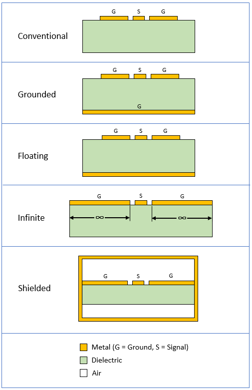
Shown below is a summary of some of the more common CPW types which will be explained in more detail later in this topic.
Conventional CPW
Alternate names: Ungrounded CPW, Classic Coplanar Waveguide, Finite ground CPW (FGCPW, FG-CPW), and Finite Width Ground CPW (FW-CPW).
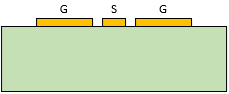
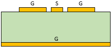
The most common type of CPW transmission line is called "Conventional" CPW. It is composed of three coplanar conductors, one signal conductor and two finite-width ground return conductors on top of a dielectric substrate. There is no metal below the substrate. A cross-section of Conventional CPW is shown below.
To model this in Sonnet, an air dielectric should be added under the substrate as shown in the Stackup Manager view below.
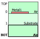
The air thickness should be large enough to minimize any coupling between the circuit metal and the bottom cover of the Analysis Box. There is typically a wide range of acceptable air layer thickness values depending on the circuit and the cover settings used. Testing is recommended to find a suitable air layer thickness.
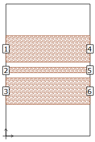
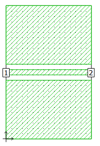
Shown below is a 2D geometry view of a typical Conventional CPW through line circuit.
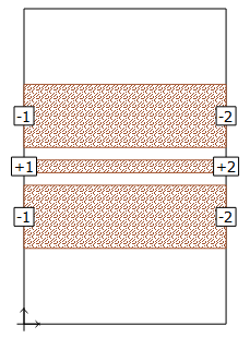
Each excitation is composed of a group of three Sonnet ports: a signal port, labeled with a positive number (e.g., "+1"), and two ground reference ports, each labeled with a corresponding negative number (e.g., "-1"). As explained in Ports with Negative Numbers, the negative numbered ports are used as the ground reference instead of the Analysis Box. To learn how to edit the port numbers, see Changing Port Numbering.
The example files cocross and cpw_filter use Conventional CPW ports and may be accessed using the Example Browser.
Sufficient space should be created between the outer conductors and the adjacent Analysis Box walls. If an outer conductor edge extends to the adjacent wall, some of the ground return current that should flow through the outer conductor will flow through the wall instead.
The above example is a simple transmission line that is electrically short. For more complex circuits, you should periodically place an electrical connection (e.g., air bridge) between the two outer conductors to suppress multi-mode propagation.
Grounded CPW
Alternate names: Conductor-backed CPW (CB-CPW), Finite Ground Plane CPW (FGCPW), Finite Width Conductor Backed CPW (FW-CBCPW), and GCPW.
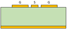
Another common type of CPW transmission line is called "Grounded" CPW. It is composed of three coplanar conductors, one signal conductor and two finite-width ground return conductors on top of a dielectric substrate. In addition, it includes a metal ground plane below the substrate that is electrically connected (usually with vias) to the two outer conductors. A cross-section of Grounded CPW is shown below.
To model Grounded CPW, allow the excitation ends of the two outer conductors to touch the Analysis Box walls and only attach ports to the signal conductor. Do not add an air layer below the substrate. Set the Analysis Box bottom cover to a lossless or lossy conductor, to represent the lower ground plane. The box walls electrically connect the ground return conductors to the box bottom cover at the port excitation plane.
To minimize the interaction between the ground return conductors and the adjacent Analysis Box walls, sufficient space should be created using the box size. Shown below is a 2D geometry view of a typical Grounded CPW through line circuit.
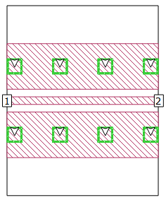
Vias have been added to force the potential of the two outer conductors and ground plane to be equal. Without the vias, electrically long Grounded CPW structures may result in unexpected resonances (both in Sonnet and in measurements). The vias are also touching the box wall to force the port calibration standards to include vias. Please see A CPW Example for more details.
Floating CPW
Alternate names: Finite ground CPW (FGCPW), and Finite Width Conductor Backed CPW (FW-CBCPW).
Floating CPW is another type of CPW transmission line. The conductors and substrate are constructed the same way as Grounded CPW, except there are no vias or other electrical connections between the ground return conductors and the metal plane below.
This type of CPW line is often problematic because the metal plane below the substrate can "float" at a different potential from the two outer ground conductors. If the transmission line is long with respect to a wavelength, unexpected resonances can occur.
A cross-section of Floating CPW is shown below. Notice that the lower metal plane is not labelled with a "G" because the lower metal plane is not grounded.
Floating CPW is modeled the same way as Grounded CPW, except that negative ports must be attached to the excitation edges of the ground return conductors (see Conventional CPW for an explanation of the port setup). Shown below is a 2D geometry view of a Floating CPW transmission line.
The example file cpw_spiral uses the Floating CPW configuration and may be accessed using the Example Browser.
Infinite CPW
Alternate name: Semi-infinite CPW.
Many textbooks and transmission line calculator tools base their solutions on theoretical, Infinite CPW equations. With Infinite CPW, the dielectric and two outer conductors extend to infinity as shown below.
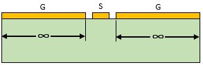
An infinite CPW transmission line is not practical to fabricate, but it is included here because it is sometimes beneficial to compare Sonnet to a transmission line calculator or textbook equation.
To approximate Infinite CPW in Sonnet, the two outer ground conductors must be truncated to a large, but finite width. To determine a suitable width, simulate a series of models with increasing outer conductor width values. Then compare the results to determine at which width value the characteristic impedance and S-Parameter data converges.
Infinite CPW is actually a special case of either Conventional, Grounded, or Floating CPW. Please see the corresponding section above for a description of how to configure the ports, define the dielectric stackup, and set the Analysis Box covers.
Shielded CPW
Alternate name: Shielded Suspended CPW.
There are many variations of Shielded CPW, but one common characteristic is that the CPW transmission line is fully shielded on all sides. The shield is straightforward to model in Sonnet using the Analysis Box with the appropriate box size and cover settings. The Grounded CPW described above can be modeled as Shielded CPW using this approach.
Another common Shielded CPW configuration is where the substrate is suspended within a metal cavity as shown below. Air layers are required above and below the substrate to suspend it. Usually, the outer conductors are connected to the cavity sidewalls, thereby connecting all possible ground return bodies together.
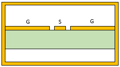
To model Shielded CPW, allow the excitation ends of the two outer conductors to touch the Analysis Box walls and only attach ports to the signal conductor. An example is shown below.
Unbalanced Excitations
All the above examples assume that the circuit will be excited by a balanced CPW signal. Although this is the typical case, there are some situations where the excitation is unbalanced. One example is when a complex CPW circuit is subdivided into smaller subcircuits and each subcircuit is analyzed in Sonnet. Even though a balanced CPW signal is applied to the inputs and outputs of the full CPW circuit, the signal may become unbalanced within the circuit because of asymmetries in the layout. If this occurs, the subcircuits should not be excited with a balanced signal.
Another example is when you import Sonnet results into a circuit simulator that contains an unbalanced feed network.
To address these situations, uniquely numbered ports should be applied to the CPW circuit/subcircuits. This port configuration allows all possible modes including balanced and unbalanced modes. An example of a CPW with uniquely numbered ports is shown below.