Adding a Standard Geometry
Sonnet provides some standard artwork elements which can be quickly and automatically created with parameters you specify. The available elements depends on the type of Tech Layer being used.
- Planar Tech Layers: Includes rectangles, parallel lines, circles, ellipses, donuts, spiral inductors, meander lines, fan stubs, interdigital capacitors, and Lange couplers.
- Via Tech Layers: Includes rectangles and circles.
- Brick Tech Layers: Includes rectangles.
Procedure
The general procedure is the same for all standard geometry elements and is as follows:
In the Stackup Manager, select the Tech Layer with which you wish your standard geometry to be associated.
The Tech Layer is highlighted.
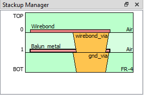
Balun_metal Tech Layer selected
Some planar standard geometries require more than one Tech Layer. In those cases, the selected Tech Layer is used for the primary layer. You will need to select the other Tech Layer(s) from a drop-down list in the standard geometry's dialog box.
In the Project Editor's Insert menu, select either Planar, Via, or Brick, followed by the name of the standard geometry you wish to add.
The corresponding Properties dialog box appears.
Change the values and settings in the Properties dialog box.
Most of the settings are defined in the diagram to the right of the settings. See Geometry Element Parameters for settings that are not defined in the diagram. If you need a new Tech Layer, you may select <New Tech Layer> and you will be prompted for the properties of a new Tech Layer.
Click OK.
Your cursor changes to to a blue cross and an outline of the geometry is displayed and it moves with your cursor. The outline represents the location where the geometry will be placed when you click your mouse.
Place your cursor where you wish the geometry element to be located and click the mouse button.
The geometry element is added to your layout.
Geometry Element Parameters
Most geometry element parameters are defined in the diagram to the right of the parameters. The following is a list of parameters or settings which are not defined in the diagram.
Num. Sides: The Number of Sides setting specifies the number of line segments used to define the outer edge and, when applicable, the inner edge of the object. For the N-Sided Spiral, it sets the number of line segments used to create the outer and inner edge of the trace, per turn. For the Circle/Ellipse, it sets the number of line segments used to create the outer arc. For a full, 360 degree Donut, it sets the number of line segments used to create the outer and inner arcs. For a partial Donut, a fraction of the number of segments used in a full 360 degree arc are removed. For all these objects, the line segments are joined to create an n-sided polygon.
X Justify and Y Justify: These fields are used to control the object insertion point. The X coordinate is the Left, Center, or Right plane of the object bounding box. Similarly, the Y coordinate is the Top, Center, or Bottom of the object bounding box. During placement, the insertion point is indicated with a blue cross and it follows the mouse cursor.
Bridge: This field is used for spiral inductors. If set to Yes, a rectangular bridge is created using the specified Bridge Tech Layer. Square vias, using the specified Via Tech Layer, are created, connecting the Bridge metal to the Spiral metal.
Number of fingers: This field specifies the number of fingers in the Lange coupler. The first and last fingers are half length and count as only one total finger. Only even numbers of 4 or more are allowed.
Length Units: This field displays the Length Units for the project. These units are used for the length parameters which define this geometry element. The Length Units value may only be changed by selecting Circuit > Settings > Units.
Angle: All angles have units of degrees.