Basic Polygon Editing
This topic provides the details for selecting and editing polygons in your geometry project file.
Selecting Polygons or Points
Modes
To select polygons, you need to be in Pointer mode. To select the points of a polygon, you need to be in Edit Points mode.
Pointer mode: Pointer mode is the default mode. If you are in another mode and wish to return to Pointer mode, select Edit > Pointer or click the Pointer button in the edit toolbar: ![]() .
.
Edit Points mode: To enter Edit Points mode, select Edit > Edit Points or click the Edit Points button in the edit toolbar: ![]() . See Editing Points for more details.
. See Editing Points for more details.
Click to Select
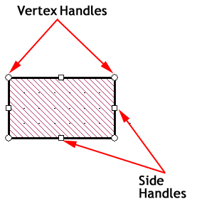
Clicking on a polygon while in Pointer mode selects the polygon. The polygon becomes highlighted with a black outline, the vertices are identified with open circles and the sides with open squares. The open circles and squares act as "handles," allowing you to resize or reshape the polygon by dragging the handle with your mouse.
You may move a single vertex of a selected polygon by holding down the Ctrl key while clicking and dragging the Vertex Handle. You may also select a point by entering Edit Points mode, followed by clicking a vertex to select it.
Separate polygons sometimes have several vertices in common. If you want to select a vertex of polygon A while in Edit Points mode, but not the coincident vertex of polygon B, place the cursor close to the vertex and just inside polygon A. The polygon A vertex is then selected.
Lassoing
To select multiple points while in Edit Points mode, or multiple polygons while in Pointer mode, lasso an area which contains these objects. To lasso an area while in the pointer or Edit Points mode, move the cursor to the upper left corner of the region you want to select and press the left mouse button without releasing it. Hold the mouse button down and drag it to the right and down. A rectangular box shows the area that will be selected. Now release the mouse button. All points or objects in the region are selected.
When in Pointer mode, there are two selection modes which affect how lassoing works. The active mode is displayed as an icon in the Mode toolbar. Clicking on the icon toggles the mode to the alternative mode.
 Surround selection mode: When in Surround mode, any polygon completely surrounded by the lasso area is selected. Any polygon that is only partially surrounded by the lasso area is not selected.
 Touch selection mode: When in Touch mode, any polygon surrounded by the lasso area is selected. Any polygon which is partially surrounded by the lasso area is also selected.
Shift and Control Keys
When performing multiple selects of polygons or points, you may add items to items that are already selected. To add items, press the Shift key while performing the select. Alternatively, you may remove items from previously selected items by pressing the Ctrl key while selecting the item(s). This applies whether you are performing selections by clicking on a single item, or lassoing a group of items.
The Shift key allows you to select additional objects, while the Ctrl key toggles the state of the objects. If it is currently selected, pressing the Ctrl key while performing a selection action will deselect the object. If the object is not currently selected, then pressing the Ctrl key while performing a selection action will select the object.
All Level Select
If your circuit has more than one metal level with polygons, you may want to modify the polygons or points on some or all of these levels simultaneously. To select points or polygons on more than one level at a time, enable All Level Select mode by selecting Edit > All Level Select or selecting the All levels checkbox in the Mode toolbar.
Pressing Ctrl+A selects all the polygons in your circuit on all levels regardless of the All Levels setting.
Deselect All
Click a blank area of your circuit to deselect all objects. You may also select Select > Select None from the Project Editor's main menu.
Select Matching Polygons
If you wish to select a group of polygons with a particular set of properties, you may use the Select Matching Polygons dialog box. There are two methods to open this dialog box.
- Select Select > Select Matching Planar Polygons, Select > Select Matching Via Polygons, or Select > Select Matching Brick Polygons.
- Select one or more polygons, and right-click one of those polygons and select Select Matching Planar Polygons, Select Matching Via Polygons, or Select Matching Brick Polygons from the pop-up menu.
If you open the dialog box when there is no polygon selected, the dialog box is opened with the value <Any> in all the input fields. <Any> functions as a wild card. Select the desired values for the fields which you wish to match.
If one or more polygons are selected in your circuit when you invoke this command, the dialog box is opened using the values of the selected polygons. If you then wish to remove one or more of the fields from consideration, enter the value <Any> or leave the entry blank for that field.
When you click the OK button, any polygons in your circuit which contain the specified parameters are selected.
Moving Polygons or Points
To move selected polygons or points, press and hold the left mouse button on one of the selected objects. With the button held down, move the mouse. The point or polygon moves as you move the mouse. Drag the polygon or point to the desired location and release the button.
Notice that, by default, objects always move in increments of a cell. If you want to move a point or polygon in increments other than a cell, you must change the snap setup. See Snap/Ortho for details.
Nudge
You may move selected polygons or points one cell at a time by using the arrow keys while holding down the Shift key. Each time you press an arrow key, the selected items are moved by one cell in the direction of the arrow.
Precise Moving
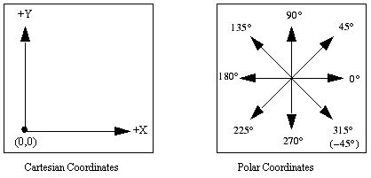
Selecting Object > Move when an object is selected, opens the Move dialog box to precisely move the object in your circuit. There are two different ways to define the movement of the object, either by defining a delta along the x and y axes, or inputting a distance and direction from the present location. When you input values into one set of controls, the other set is updated with the equivalent values. The distances you enter use the coordinate system shown below:
You may also select the Make a Copy checkbox to create a copy of a polygon at the location specified, while leaving the original object in its present location.
Another method of precisely moving selected polygons or points is to enter the values using the keyboard. See Keyboard Entry.
Editing Points
Select Edit > Edit Points to move or delete individual points or a group of points of a polygon or multiple polygons. You may also use the Edit button in the Edit toolbar: ![]() . This provides more precise control over reshaping your polygons than using the handles method described in Selecting Polygons or Points. For example, if you wish to move the edges of multiple polygons all the same distance, select all the points of the desired edges. Dragging one of the selected points causes all of the selected points to move the same distance, as shown in the animation below.
. This provides more precise control over reshaping your polygons than using the handles method described in Selecting Polygons or Points. For example, if you wish to move the edges of multiple polygons all the same distance, select all the points of the desired edges. Dragging one of the selected points causes all of the selected points to move the same distance, as shown in the animation below.
You may also cycle through each point in a polygon while in Edit Points mode. To do so, select a vertex, then hold down the Ctrl key and press the left or right arrow key. Each time you press the arrow key, the next vertex of the polygon will be selected.
Cut, Copy, Paste, and Delete
The Project Editor's Edit menu contains Cut, Copy, Paste, and Delete commands, and they function in the usual sense. For Cut and Copy, the objects are copied into the clipboard and remain in the clipboard until you replace them by doing another Cut or Copy. All objects attached to a polygon will be copied to the clipboard along with the polygon.
You may also cut or copy a polygon from one Project Editor window and paste it into a different Project Editor window.