mmic_stage: A Component Example
This topic uses a set of example files to demonstrate Sonnet Project Components. The example is called mmic_stage and may be accessed using the Example Browser. The example folder includes several project files and graphs which will be referred to later in this topic.
Sonnet Project Components allow you to add one or more Sonnet subprojects to your main project. All geometry subprojects are electromagnetically analyzed, and then connected to the main project using circuit theory. Sonnet Project Components use Sonnet’s Co-calibrated Port technology, providing fully calibrated internal ports. See Components for more information on Components.
Overview
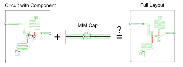
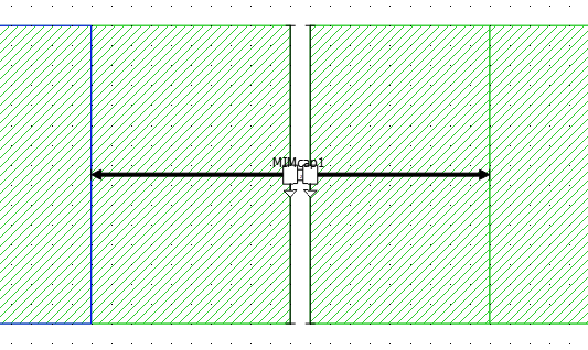
The project file, Full_layout, is an interstage matching network as shown in the picture below.
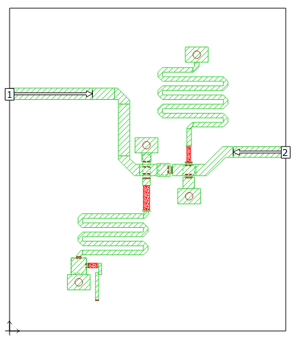
2D view of Full_layout
The layout includes an MIM capacitor which we will replace with a Sonnet Project Component.
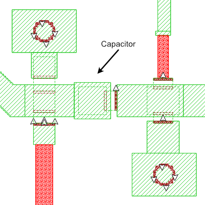
Full_layout contains the capacitor layout.
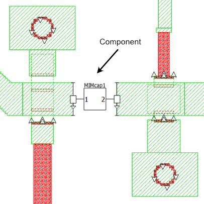
Uses_ProjComp replaces the cap with a Component
The MIM capacitor is removed from the layout and analyzed separately. This can be useful if you want to analyze the capacitor with a smaller cell size, or if you want to try several iterations of capacitor values or layouts without requiring an analysis of the full layout. Shown below is a picture of the capacitor.
MIM_cap_only is just the capacitor
The capacitor's dimensions have been parameterized to allow for a parameter sweep. Parameterization will be discussed later in this topic.
You add a Project Component in the Project Editor using Insert > Component > Sonnet Project.
Component Properties
The properties of the Component are as follows:
- Project File: The Component refers to the capacitor project, MIM_cap_only.sonx.
- Parameters: The default settings were used for the parameters. Parameters will be discussed in detail in the Parameter Sweep section of this topic.
- Ground Reference: The Ground Reference is set to Auto. Sonnet uses the nearest available ground. In this case, the nearest ground is the bottom box cover. The port symbol shows a triangle pointing down, indicating that the ground reference is below the present level.
- Port Properties: Double-clicking on the port shows the port properties. All properties are set to the default values.
For more information about any of these properties, please refer to Components.
Initial Results
The project with the Component, Uses_ProjComp, is analyzed and the results are compared with the original project, Full_layout. If the projects are de-embedded accurately, and if there is no coupling between the capacitor and the rest of the circuit, the project with the Project Component should give the same results as the full layout.
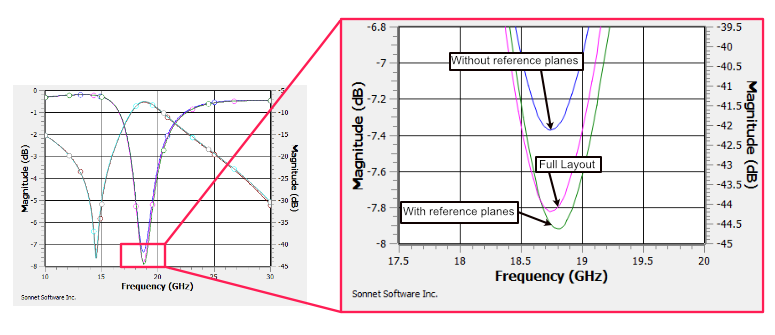
 The results of the two simulations are shown below.
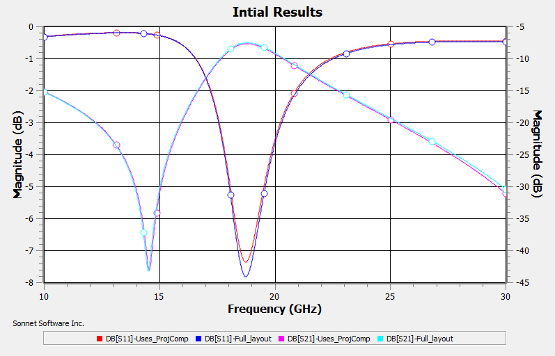
Very good agreement is found for both magnitude and phase. Only magnitudes are shown here. There is a small error in dB[S11] at about 18.7 GHz. The next section investigates this error and proposes an improvement to the results.
Improving the Results
The main difference between the full layout project and the one using the Component is that the coupling between the capacitor and the rest of the circuit is modeled with the full layout but is not modeled when using the Component. This is because the capacitor metal was removed in the project using the Component.
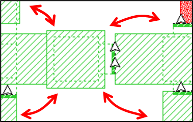
Full layout includes coupling
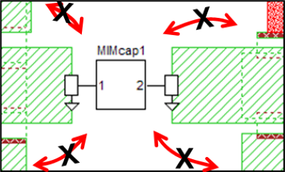
No coupling when Component is used
Since the two cases give very similar results, the coupling between the capacitor and the rest of the circuit must be quite small. But we can increase the coupling to the component by adding some of the missing metal back in. If done correctly, this should improve the accuracy of the results.
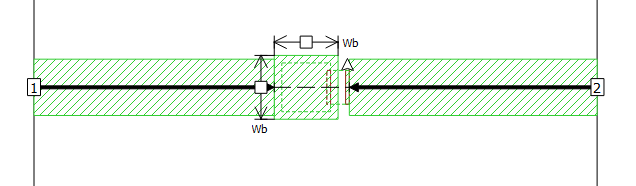
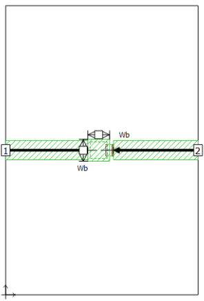
The figure below shows a closeup of a new project (Uses_ProjComp_RefPlanes) with metal polygons added to the layout to approximate the capacitor metal. The Component is then added in the one-cell gap between the two new metal polygons. Reference planes have been added because the actual capacitor metal is modeled in the capacitor subproject. Without the reference planes, the capacitor metal would be modeled twice.
A reference plane does not remove metal from the layout. Instead, it negates the length of transmission line equal to the length of the reference plane. If you are unfamiliar with this concept, please see A Common Misconception.
The graph below shows the improved results when using this technique.
Parameter Sweep
If you want to sweep the dimensions of the capacitor you could parameterize the project containing the full layout and sweep the parameter values. This would require a full EM simulation for each capacitor dimension. An alternative to this approach is to use the project with the Component and parameterize the capacitor subproject. The subproject would be EM simulated for each parameter combination of the parameter sweep, but the main project would need to be simulated only once. This can greatly reduce the total analysis time required with only minimal effect on the accuracy as shown in the previous section.

Simulated once
Simulated many times
Capacitor Subproject
The capacitor subproject uses two parameters. Wt is the width of each side of the top plate, and Wb is the width of each side of the bottom plate
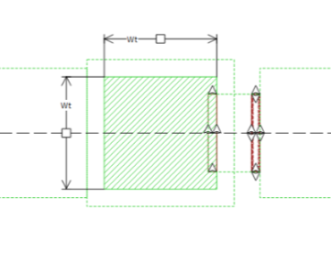
Top plate
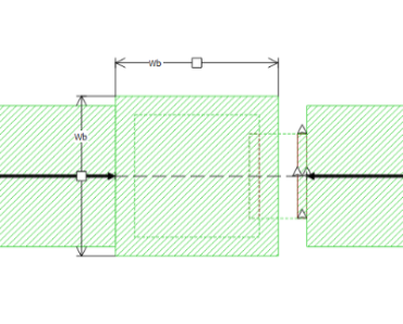
Bottom plate
Main Project
By default, in the main project, the parameters of the Component are set to the nominal values from the subproject: Wt = 65 microns and Wb = 85 microns. To allow the capacitor dimensions to be controlled by the main project, variables W1 and W2 were created in the main project and the Component was edited so that Wt = W1 and Wb = W2.
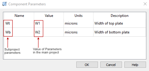
The names of the variables were intentionally chosen to be different from the variables of the subproject Wt and Wb. This was not necessary for this case, but is good practice, especially when working with multiple Components that refer to the same subproject.
If you have a project with multiple capacitors, you could use a single parameterized subproject for the capacitor. This could reduce total analysis time of parameter sweeps.
Parameter Sweep Setup
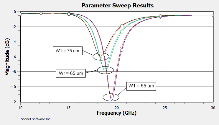
The main project, ParamSweep, contains a parameter sweep of three values of W1 and two values of W2, resulting in a total of six parameter combinations. Since W1 and W2 only affect the subproject, the main project is analyzed only once, but the subproject is analyzed six times. When the analysis is completed, the main project will contain results for the six parameter combinations, even though it was simulated only once.
Shown below is a graph of dB[S11] for the six parameter combinations. The curves are in three groups. Changing the bottom plate of the capacitor (W2) had very little effect on the results, whereas changing the top plate (W1) did.
Summary
This example highlighted the following:
- Sonnet Project Components use Sonnet’s Co-calibrated Port technology, providing fully calibrated internal ports.
- Comparison of the full layout results to the results using a Component were very close to each other, showing that the technique works well.
- Adding metal that approximates the subproject and using reference planes can improve the accuracy.
- Parameters may be passed from the main project to the subproject, opening up a whole range of possible applications.