Components
Introduction
The Component feature is built upon the high-accuracy de-embedding technique used for Sonnet Co-calibrated Internal ports [16]. Using this technique, you may insert any of the Component types listed below:
- Data File: An S-, Y-, or Z-parameter data file.
- Ideal Component: An ideal resistor, capacitor, or inductor.
- Ports Only: Co-calibrated ports which share the same calibration group. This type of Component is identical to using Co-calibrated ports, but is sometimes more convenient for the user.
- Sonnet Project: Is used to insert another Sonnet project into your Sonnet model.
- User Model: Is used to insert a model from an external library into your Sonnet model such as a Modelithics library element.
See Component Types below for more details on each type of Component.
In all cases except the Ports Only Component type, Sonnet uses a circuit simulation technique to produce the combined results. The coupling from the inside of the Component to the rest of the circuit is not considered in the Sonnet analysis. Only the coupling from the Component’s terminals is considered.
Since Sonnet Components use Co-calibrated Internal ports, we recommend reading the topic Co-calibrated Internal Ports before proceeding.
Adding a Component
You add a Component in the Project Editor using Insert > Component followed by the type of Component you wish to add. This opens the Component Properties dialog box and the Component Assistant. Whenever you select a control in the Component Properties dialog box, the assistant provides a description of the field, and often, an illustration of the principle.
If the Component Assistant does not appear, you should click the Display Assistant button at the bottom of the Component Properties dialog box.
Anatomy of a Component
The Component is represented in your circuit by a Component symbol. The label of the Component appears above the Component symbol and the terminal numbers are identified there. Ports, indicating where the terminals of the Component are connected to the metal in your circuit, are represented by a small rectangle. Component ports are only numbered when the Component model type is Ports Only. An example of a Component, as it appears in the Project Editor, is shown below.
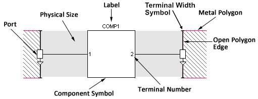 Component Symbol: This is the symbol that represents your Component in your project.
Port: The Component port defines the point at which the Component is connected to the circuit metal and must be attached to an open polygon edge. This point also serves as a reference plane for de-embedding the Component unless a reference plane is added for the port. There is one Component port for each terminal on the Component. Component ports are modeled using Co-calibrated Internal ports. For more information on co-calibrated ports, please see the topic Co-calibrated Internal Ports.
Terminal Numbers: Terminal numbers identify the physical pin on your Component connected to the corresponding Component port. If the Component type is a Sonnet project, the terminals correspond to the ports in the Sonnet project.
Terminal Width Symbol: This is the symbol that represents the Terminal Width of a Component port. See Terminal Width for an explanation.
Terminals and/or ports are numbered in the order in which they are added to your circuit but may be modified after the Component is added to your circuit by right-clicking on the corresponding port and selecting Port Properties.
Label: The label is user-defined text which identifies the Component in your circuit. Each Component label in a project must be unique.
Open Polygon Edge: Component ports may be placed only on open polygon edges. However, reference planes may be used to shift the reference plane to the interior of the polygon. For more information, see Shifting Reference Planes.
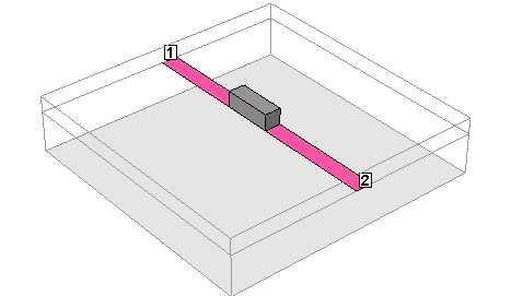
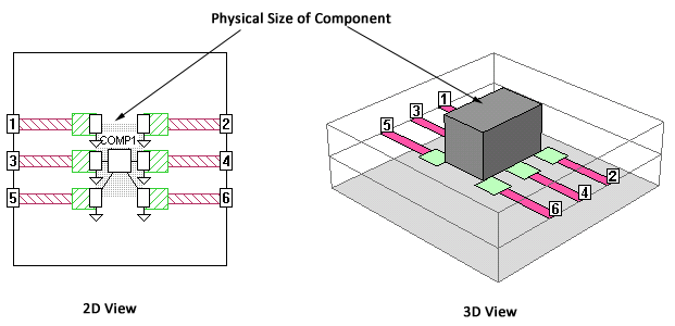
Physical Size: You may optionally enter a physical package size for your Component. These measurements (height, width, and length) are not used in the EM simulation but are there to provide a graphical representation in both the 2D and 3D view, that represent the physical size of the Component. This is especially useful for design presentations and reviews. Shown below is a 3D view of the example Component pictured above.
Component Types
Data File
The Data File Component is a Component that is modeled with a user-specified S, Y, or Z-Parameter file (Touchstone format). The data file used for your Component can be the result of another simulation or measured data from an actual component. There is no limit to the number of ports you may use for a data file Component. You add a Data File Component by selecting Insert > Component > Data File in the Project Editor.
Ideal Component
The Ideal Component is a single two-port ideal component. There are three types of Ideal Components available: resistor, capacitor, or inductor. All Ideal Components use a series element with two ports as shown below.
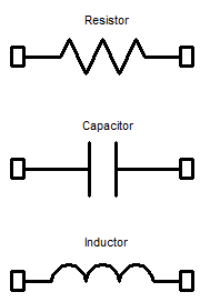
You add an Ideal Component by selecting Insert > Component > Ideal in the Project Editor.
Ports Only
Inserting a Ports Only Component allows you to insert internal ports in your circuit which may be used later in a circuit design program. All of the ports associated with this Component have a common ground and share a calibration group (see Calibration Groups). There is no limit to the number of ports your Component may have. This Component type is functionally equivalent to using Co-calibrated Internal Ports. For a detailed discussion of co-calibrated ports, see Co-calibrated Internal Ports.
You may add a Ports Only Component by selecting Insert > Component > Ports Only in the Project Editor.
Sonnet Project
Inserting a Sonnet Project Component allows you to insert a Sonnet geometry project or netlist project. If the Sonnet project used for the Component does not include analysis data, then the EM solver runs an analysis on the Component project as part of the larger analysis. There is no limit to the number of ports you may use for a Sonnet Project Component.
If the Sonnet Project contains parameters, you may open the Model Parameters dialog box by clicking the Parameters button in the Component Properties dialog box. This dialog box allows you to define the values or link the parameters in the Component project to parameters in the main project. Any change in the variables in the main project also changes the value of any parameters in the Component project that are defined by that variable.
You may add a Sonnet Project Component by selecting Insert > Component > Sonnet Project in the Project Editor.
The example mmic_stage contains a project using a Sonnet Project Component, which may be accessed using the Example Browser.
User Model
The User Model Component allows you to add a model from a library that has been purchased, or developed in-house, to your geometry. There is no limit to the number of ports you may use for a User Model Component.
If the model contains parameters, you may open the Model Parameters dialog box by clicking the Parameters button in the Component Properties dialog box. This dialog box allows you to define the values of the parameters in the User Model Component. You may enter a fixed value or use a variable defined in the main project as the value of the parameter(s). When a variable is assigned as a value, any change in the variable in the main project also changes the value of the parameter in the Component project.
You add a User Model Component by selecting Insert > Component > User Model in the Project Editor. This command opens the Components Properties dialog box. The model library opened is set using Admin > Third Party Interfaces > User Model. Modelithics models are presently the only supported vendor models, although it is possible to create custom models. If you are interested in doing so, please contact your Sonnet Software representative for details.
Use of the Modelithics library requires a Modelithics license. You may purchase this from Modelithics, Inc.
Multi-level Components
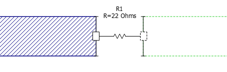
Components are not limited to a single level. The terminals of the Component may be on multiple levels. In the picture below, a resistor Component is connected between two polygons on two different levels. The terminal on the level that is not the present level is shown with a dashed outline.
Component Properties
An important part of modeling a Component in Sonnet is to consider the conditions under which the measured data or model for your Component was obtained. These conditions should be used to determine:
- The type of ground reference
- The Terminal Width
- If reference planes are used for the Component ports and if so, of what length
Your Sonnet project should be set up to use the Component in the same manner that the Component was measured or modeled. Most of these settings are discussed in the topic Co-calibrated Internal Ports since Sonnet Components use Co-calibrated ports. We recommend reading that topic before proceeding. The sections below cover information that is specific to Sonnet Components and is not covered in the Co-calibrated Internal Ports topic.
Ground Reference
The measurement or model of your device used for the Sonnet Component has a common ground reference. You must decide where this common ground should be connected in your Sonnet project. For example, if the measurement's ground reference was the ground plane at the bottom of the substrate and you wish to connect this ground reference to the bottom box cover of your Sonnet project, you should choose Box Cover for the Component's ground reference and set the Ground Direction of each port to Below.
There are five choices for the Ground Reference: Auto, Sonnet Box, Polygon Edge, Polygon Plane, and Floating. All of these choices are covered in Co-calibrated Internal Ports except Polygon Plane which is described below.
Polygon Edge(s)
When your ground reference is set to Polygon Edge(s), the ground reference of your Component is connected to one or more polygon edges selected by you when adding the Component. You may specify as many ground references as you need.
Examples of this are:
- Transistor data without parasitics to ground, but with a ground path included in the Sonnet circuit
- A multi-pin module with one or more ground pins
The Polygon Edge(s) ground node connection is only available for Data File and Sonnet Project type Components.
Component Port Properties
Some Component properties are properties of each Component port. If a Component has multiple ports, each port may have different port properties. You set the port properties by double-clicking the Component's port or by selecting a Component's port and selecting Object > Port Properties.
Terminal Width
The Terminal Width is the electrical contact width of the real device that you are modeling with a Sonnet Component. Entering a Terminal Width allows you to accurately model the current flow from the circuit geometry into the Component. See the Terminal Width section of the Co-calibrated Internal Ports topic for a complete description.
Reference Planes
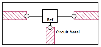
Components require their ports to be on open polygon edges. Reference Planes can be used to effectively move your port position away from the polygon edge. To accomplish this, the EM solver uses circuit theory to cascade a negative length of the line with the analysis results. If no reference plane is specified, then de-embedding the Component removes none of the feedline metal but the port(s) are still de-embedded. The use of reference planes is illustrated below.
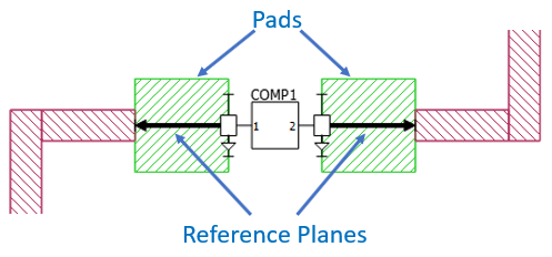 All the Component ports on a side of a Component use the same reference plane. For a detailed discussion of reference planes and de-embedding, please see Shifting Reference Planes.
The reference planes for Component ports are set in the Component Port Properties dialog box. This dialog box may be opened by double-clicking on a Component port or by selecting the Component port and selecting Object > Port Properties.
You may not set a reference plane for a Component port if your Ground Reference is floating.
Calibration Lengths
The EM solver will automatically determine appropriate lengths for the calibration standards used in the de-embedding algorithm. Normally, the default Auto setting produces efficient and highly accurate simulation results. In rare cases, you may wish to manually override the automatic lengths. Before manually overriding these settings, please be sure to read the Calibration Standards topic.
The calibration lengths for Component ports are set in the Component Port Properties dialog box. This dialog box may be opened by double-clicking on a Component port or by selecting the Component port and selecting Object > Port Properties.
Physical Size
You may enter a physical size for your Component for display purposes. The physical dimensions length, width, and height, are not used in the simulation, but affect how your Component is displayed in the Project Editor. You may enter the precise dimensions or select Auto to have the software estimate the dimensions based on your Component’s port placements. An example is shown below.
Analyzing Components
Data File Frequencies
When using a data file Component type, frequencies in your data file do not need to precisely match the Sonnet analysis frequencies. The EM solver will interpolate between data file frequencies if necessary, but it will not extrapolate outside the frequency range of the data file.
Rerunning an Analysis
When the EM solver analyzes a circuit with a Component, it first performs an electromagnetic analysis of the geometry, then uses circuit theory to connect the Component to the geometry. If you change the data file used for a Component or the value and/or type of an Ideal Component, in subsequent analyses, the solver will perform only the circuit theory part of the analysis, significantly reducing processing time. Please note that any graphs of the response are not automatically updated. Instead, you need to select Graph > Refresh to update your graph.
For Sonnet Project Components, the solver runs an analysis on the Component project as part of the analysis of the main project and stores analysis results for the Component project. The data resulting from the analysis of the Component project is then used in the circuit theory part of the main analysis. This data will be reused as long as no changes are made to the Component project.
See Also