The Analysis Grid
Sonnet's subsectioning is based on a rectangular unit called a cell. One or more cells are automatically combined together to create subsections. Cells may be square or rectangular (any aspect ratio), but must be a consistent size over your entire circuit. When viewed in the Sonnet Project Editor, a cell is represented by the small dots in the Project Editor window. The small dots are placed at the corners of each Cell forming an analysis "grid".
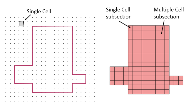
A metal polygon with the cell grid is shown on the left. The same metal polygon’s subsectioning is shown on the right. Note that some subsections are comprised of only one cell, while other subsections are made up of multiple cells.
To set your cell size using the Sonnet Project Editor, select Circuit > Settings > Box from the Project Editor main menu.
Snapped Fill
By default, the Sonnet Project Editor displays polygons with an outline and a Snapped Fill pattern. The outline represents the exact geometry that you entered or imported. The Snapped Fill represents the actual subsections analyzed by the EM solver. When the polygon is not aligned with the grid, the actual subsections analyzed by the EM solver may differ from the input geometry as illustrated below.
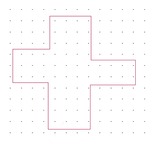
Snapped Fill off
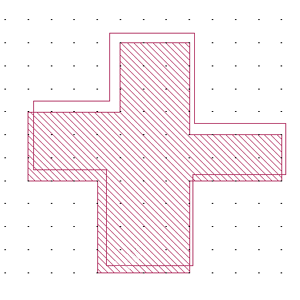
Snapped Fill on
You turn the Snapped Fill on and off by selecting View > Polygon Fill > Snapped Fill and View > Polygon Fill > No Fill in the Project Editor. See Polygon Fill for details and for additional viewing options.
If the dots representing the cells are very close to each other, the grid is automatically hidden from view. To see the grid, zoom into an area.