Antennas

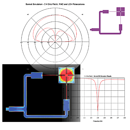
2.4 GHz Patch Antenna with S-parameters, current density and far-field radiation pattern shown.
A RH circularly polarized patch antenna design for operation at 2.4 GHz, with quadrature phase feed. Sonnet provides precise S-parameters, current density and far-field radiation pattern (both RH and LH circular polarizations are shown for the x-axis cut). See "Patch Antennas, Measured vs. Calculated" below for more details.
Patch Antennas, Measured vs. Calculated
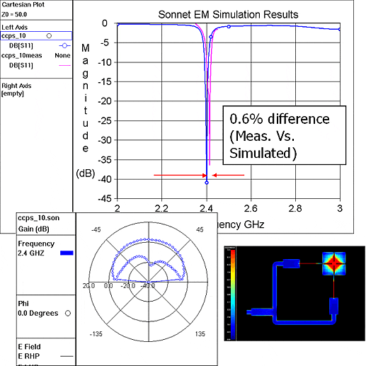
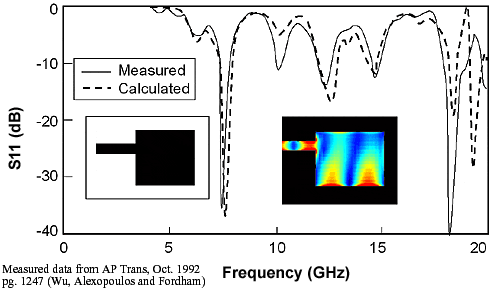
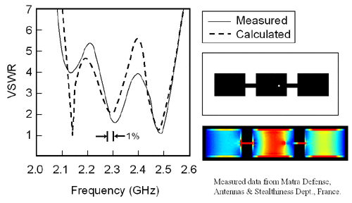
Here are three examples of patch antenna simulations using Sonnet. As shown in the graphs, the calculated result are very close to the measured results.
Circularly Polarized Patch Antenna
This right-hand circularly polarized patch antenna was designed for operation at 2.4 GHz, with quadrature phase feed. Sonnet provides precise S-parameters, current density and far-field radiation pattern (both RH and LH circular polarizations are shown for the x-axis cut).
Edge Fed Patch Antenna
This is a typical patch antenna. Notice that the calculated reflection coefficient is a reasonably good match with calculated data. This analysis is swept through many modes, not just the first mode. At the high end of the frequency range the cell size is too large with respect to wavelength. Also shown is the layout of the patch on the left and the current distribution at 13 GHz on the right. In the current distribution, red represents high current and blue represents low current.
Triple Patch Element
This is a triple patch antenna from Matra Defense, France. The three patches have slightly different sizes so that the bandwidth is larger. As shown in the layout, the antenna is fed with a coax probe on the right side of the center patch. Again, the agreement between measured and calculated is typical for an FFT based analysis. The current distribution is shown for 2.3 GHz. As with all current distribution results, always look for smooth current with very high current at the edge of all conductors. The high edge current is called the “edge singularity”. If the edge singularity is not seen or if the current distribution looks ragged, then there are problems with the analysis.


