Via Simplification
Several manufacturing processes used to produce RF circuits utilize via arrays or bar via groups to provide the trace metal layer-to-layer connections. Both of these types of vias may present an analysis challenge that drives the Sonnet model memory and analysis time requirements beyond what is practical to analyze. Via simplification provides an approach to via arrays and bar vias that reduce the time and memory requirements with minimal impact on accuracy.
Via Array Simplification
Via arrays may be simplified during the translation process when using an interface or translator. During simplification, arrays of vias are replaced by by fewer, larger via polygons using the Array metal model.
By default, vias are not automatically simplified. To simplify via arrays when using a translator, select the Simply Via Arrays checkbox in the Import Wizard. To simplify vias using the the Keysight ADS Interface, select the Simplify Via Arrays checkbox in the Options dialog box.
Simplify Via Array Options
There are five control options for the simplify via array feature which are discussed in detail below. The default values were determined based on extensive testing, and in the majority of cases will provide reasonable via simplification behavior. However, Sonnet handles a wide range of layouts and processes, so these controls were provided so that you can customize the translation if it proves necessary.
Minimum Vias in Array
This control defines the minimum number of vias which can be considered part of the same array. The default value for this setting is 5, so that only arrays with 5 or more vias will be considered for simplification.
Maximum Distance to Size Ratio
This control defines the maximum distance between vias which can be considered part of the same array. While the distance between vias is measured from the center lines of the individual vias, the control is a ratio of distance to via size. This distance cannot exceed the value of this ratio multiplied by the via size. The larger the value, the more widespread the vias can be and still be grouped in the same array. Since individual vias can be of any shape, the square root of the via area is used as the via size.
Maximum Size to Size Ratio
This control defines the maximum allowable difference in via size to be considered part of the same array. The larger the value, the greater the difference of via size is allowed within an array. Since individual vias can be of any shape, the square root of the via area is used as the via size. If you wish to limit your arrays to vias of the same size, set this control to 1.0.
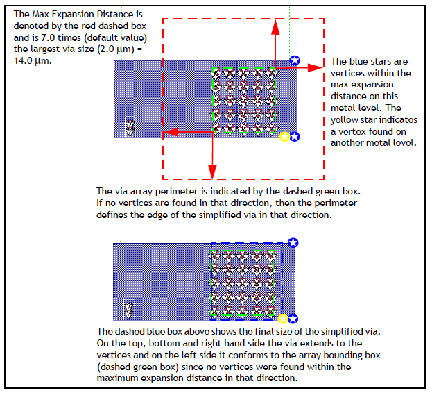
Max Expansion Coefficient
This control helps define the size of the resulting simplified via by allowing it to be larger than the original via array perimeter (also referred to as the "bounding box"). The default value is 7.0, which allows the simplified via to expand outward by a factor of 7 times the largest via size in the array. The advantage in expanding the simplified via is that it can often be sized to match the planar polygons to which the via attaches. Having the via polygon edge and planar polygon edge in alignment can significantly reduce the subsection density in the region and thereby reduce the memory requirement and analysis time of the simulation. If you wish the simplified via to be the bounding box around the array, set the Max Expansion Coefficient to 0, which allows no expansion.
An example is shown below. The algorithm looks outward from an imaginary rectangle (bounding box) drawn around the perimeter of the array (green rectangle). The distance the algorithm looks from the perimeter is the Max Expansion Distance (shown in red arrows). It is equal to the Max Expansion Coefficient times the largest existing via in the array. If a vertex from a pad polygon is encountered within this window (red rectangle), the expansion stops and this sets the simplified polygon edge. If no vertices are found in a particular direction, the edge of the simplified via rolls back to the existing via array perimeter. Please note that all metal levels are examined when looking for vertices within the maximum expansion distance.
Merge Planar Polygons During Simplify
In order to be considered an array, a group of vias must connect to a single polygon on the top and bottom of the group. When this control is enabled,the polygon pads/traces are merged prior to simplifying the vias. This results in larger arrays being recognized leading to the least number of simplified vias, thereby producing the most efficient model. This option is enabled by default. The polygons are only temporarily merged for via simplification and will not be merged in the resulting Sonnet project.
Bar Via Group Simplification
Bar vias are vias whose length is significantly longer than their width. For a description of bar vias see Bar. The Identify Bar Vias feature identifies bar vias during translation based on length to width ratio entered by the user. These via polygons are assigned the Bar meshing but their geometry is not changed. During the analysis, single or multiple adjacent bar vias are identified as a bar via group and merged into one wider via. If you wish to see the actual metal for the simplified bar vias that are used in the simulation, you should view the subsections (View > View Subsections).
By default, bar vias are not automatically identified. To identify vias when using a translator, select the Identify Bar Vias checkbox in the Import Wizard. To identify bar vias using the the Keysight ADS Interface, select the Identify Bar Via Vias checkbox in the Options dialog box. You may use the default length-to-width ratio of 2.5 or enter a custom value.
Metal used for bar vias should always use the Volume loss model since this model supports horizontal current. Any vias that use the Array loss model or the Surface loss model will not be identified as bar vias during the simplification process.
Additional Via Options
This text entry box should only be used at the direction of a Sonnet representative.