Import Wizard
The Import Wizard is used to import a DXF, GDSII, Gerber, or ODB++ file. To start the wizard, go to the Session tab and select File > Import, followed by DXF, GDSII, Gerber, or ODB++.
Import File Page
The Import File page allows you to select the project to which you wish to import the file. The page looks similar to the picture below.
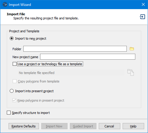
Import to new project: Select this radio button if you wish to import your file to a new Sonnet project. Enter the folder and name of the new project file to which you wish to import the file.
Use a project or a technology file as a template: Select this checkbox if you wish to use a project file or Technology File as a template. Click the browse button to select the template file. If using a Technology File, the translated project will use the stackup information from the Technology File. If using a project file, it will use the stackup, import settings, and project settings (such as frequencies and EM Options) from the template file. See the Import Status page for more details.
Copy polygons from template: If your template file is a Sonnet project file containing polygons, you may select this checkbox to copy the polygons from the template file to your translated project.
Import into present project: If you were editing a project when you selected the Import command, this radio button will be enabled. If this radio button is selected, then the polygons from the source file will be imported into your present project.
Keep polygons in present project: If this checkbox is selected, the imported polygons will be added to the existing polygons in the present project. If the checkbox is not selected, all existing polygons in the present project will be replaced by the imported polygons.
Specify structure to import: This checkbox only appears when you are importing a GDSII file. GDSII files may contain more than one structure. By default, the software selects the highest structure in the hierarchy. Occasionally, if your GDSII file contains multiple structures, you may wish to specify a different structure than the default one. Selecting this checkbox causes the Import Structure page of the Import Wizard to be opened next to specify the desired structure.
Guided Import: Click the Guided Import button to continue to use the wizard. It will walk you through a series of pages, allowing you to specify import settings. The Next and Back buttons are used to navigate the wizard.
Import Now: If you have specified a template file that contains all the necessary information to perform an import, the Import Now button will be available. Clicking it immediately performs the translation and skips the rest of the Wizard.
Import Structure Page (GDSII only)
The Import Structure page allows you to select which structure in the GDSII file you wish to convert to a Sonnet project. This page only appears if you selected the Specify structure to import checkbox on the Import File page of the wizard.
The Import Structure page displays a list of all the structures in the GDSII file. The entry of the default structure determined by the software (the structure highest in the hierarchy) is followed by "(Default)" to identify it. No action needs to be taken if this is the desired structure you wish to import. If you wish to import a different structure, select it from the list. When the GDSII file is imported, this structure is the one translated to a Sonnet project.
Layer Mapping Page
The Layer Mapping page is used to map the layers from the source file to Sonnet Tech Layers. Examples of the Layer Mapping page are shown below.
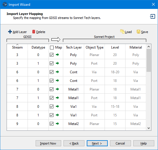
Layer Mapping page for GDSII import
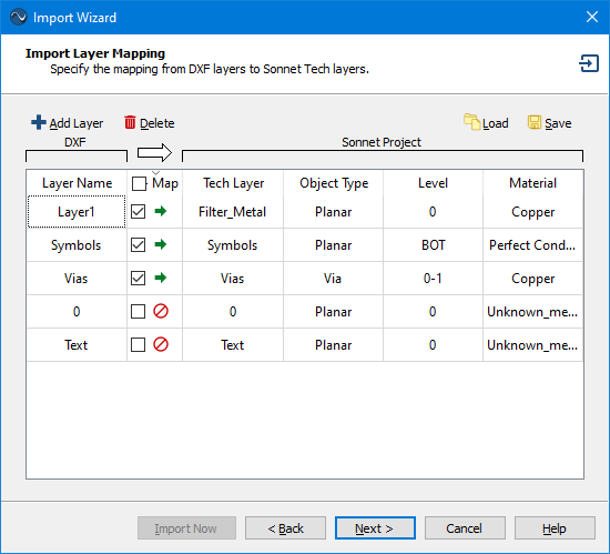
Layer Mapping page for DXF import
The column(s) to the left of the white arrow  refer to the source file and the columns to the right of the white arrow refer to the translated Sonnet project file. The Import Wizard reads the layer information from the source file, then populates the left portion of Layer Mapping page with the layer information. If you are using a template file or importing into an existing Sonnet project, then the right portion of of the page will be filled in with default values from the template file or the existing Sonnet project.
Editing the Layer Mapping
You may edit your layer mapping in the following ways:
- You may use the Map checkbox to select which layers in the source file you wish to map to Sonnet Tech Layers. If the checkbox is selected, the polygons associated with the source layer will be translated to the corresponding Sonnet Tech Layer. If you wish to map all the layers, select the checkbox at the top of the column under the white arrow.
- You may change the Tech Layer to which the source layer is mapped by selecting a new Tech Layer from the drop-down list or entering a new name.
- You may change the Object Type, level, and material of a new Tech Layer but not a pre-existing Tech Layer. For vias, you input a range of levels. For example, a via which extends from level 2 upwards to level 0 would be 2-0. Use BOT and TOP to refer to the bottom and top box covers. A via extending from level 3 up to the top cover would be 3-TOP.
- You may click the
 Add Layer button to add another entry row. Additional rows allow you to map a single source layer to multiple Tech Layers.
 - You may click the
 Delete button to delete the presently selected row.
Automatic Port Placement
Ports may be placed on your layout after the translation has completed. However, under some circumstances, you may wish to automate the port placement. The procedure requires you to edit your source file before translation.
Automatic port placement is not available for Gerber or ODB++ translations.
Using your CAD tool, create a new drawing layer.
You should choose a name for the drawing layer that helps you remember that its purpose is for ports. For example, for DXF, you may wish to call it "M3P" if the port is to be placed on layer "M3". For GDSII, you may want to use the same stream number as the metal to which you are attaching a port but use a different datatype.
Optional: For each port, create a cell or block with a name starting with "SonPort_".
Create a cell or block and name it “SonPort_#”, where the # is the port number desired, e.g., “SonPort_0”, “SonPort_1” or “SonPort_-1”. You may also include the type of port in the name by using the keywords "Box", "CoCal", or "Gap" to represent a Box-wall, Co-calibrated, or Delta Gap port, respectively. For example: Use "SonPort_Box_2" to specify port 2 as a Box-wall port.
You may omit this step if you want Sonnet to number your ports in the order they are read in the file.
For each port, add a rectangle that overlaps the polygon for each port on that layer.
The rectangle should be created on the drawing layer created in the first step. If you created a cell or block in the previous step, the rectangle should be created in the cell or block corresponding to the desired port number. The rectangle should be smaller than the polygon edge that it overlaps.
If multiple ports have the same number, copy the instance of that cell or block to where you want the ports.
If you have ports on other layers, repeat the above steps for those ports.
When importing, set the Purpose to Port, and map it to appropriate Tech Layer.
In the Purpose column of the Layer Mapping page of the Import Wizard, select Port from the drop-down list. In additional select the Tech Layer for the port.
Shown below are a DXF and GDSII example, where port 1 and 2 need to be attached to a polygon on Tech Layer M3, and port 3 needs to be attached to a port on Tech Layer M7.
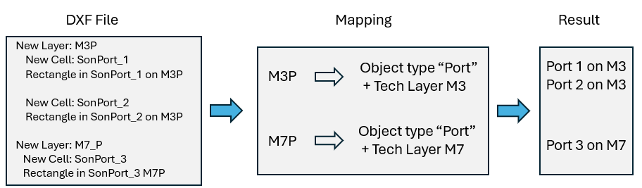
Automatic port mapping example for a DXF file.
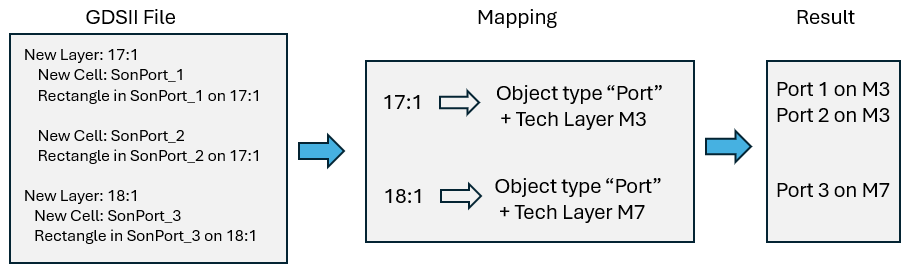
Automatic port mapping example for a GDSII file.
Saving and Loading Layer Mapping
You may also load or save a layer mapping file using the ![]() Load and
Load and ![]() Save buttons. It is normally preferable to use a template file for your imports since more information may be included in a template file than in a layer file. The layer file is maintained for backward compatibility.
Save buttons. It is normally preferable to use a template file for your imports since more information may be included in a template file than in a layer file. The layer file is maintained for backward compatibility.
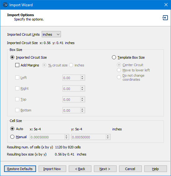
Import Options Page
An example of the Import Options page is shown below.
Settings
Imported Circuit Units: This setting is used to specify the units that are used in the input file. Most DXF files and some GDSII files do not contain units, so you may need to specify the length unit that was used when the file was created. Note that the extents of the imported circuit in the chosen length units is displayed directly below this drop-down list.
Box Size Section
This section of the Import Options dialog box controls the Analysis Box size of the resulting Sonnet project. You may specify the Analysis Box size based on the size of the circuit size, the template box size (if using a template), or the present project (if importing into your present project). These options are detailed below. The resulting box size is reported at the bottom of the page.
Imported Circuit Size
Click the Imported Circuit Size radio button if you wish to base the Analysis Box size on the physical size of the imported circuit. A bounding box is placed around the imported polygons and the size of the bounding box is used as the base size of the box.
Add Margins: If you wish to expand the box to be bigger than the size of the bounding box, you may add margins to the box size. There are two methods for defining the size of the margins, as described below.
- % Circuit Size: If this radio button is selected, the value entered for the selected margin should be the desired percentage of the circuit size. For example, if your circuit is 50 microns by 50 microns and you enter 10, then the box size will be increased by 10% (5 microns) in the direction of the selected box wall.
- <Units>: This radio button is labeled with the present length units for the project. If this is selected, enter the desired length by which you wish to increase the box size in the direction of the selected box wall.
Template Box Size
Click the Template Box Size radio button if you wish to use the box size of the template project as the box size for your translated project. This radio button is only enabled if you are using a project as a template for the import. You have three choices as to where to place your translated circuit in the box:
- Center Circuit: Places the center point of the circuit in the center of the box.
- Move to lower left: Places the lower left hand corner of the circuit in the lower left hand corner of the box.
- Do not change coordinates: Uses the same location as the source file with the lower left corner of the Analysis Box defined as (0,0).
Present Project Box Size
Click the Present Project Box Size radio button if you wish to use the box size of the your present project as the box size for your translated project. This radio button is only enabled if you are importing into your present project. You have three choices as to where to place your translated circuit in the box:
- Center Circuit: Places the center point of the circuit in the center of the box.
- Move to lower left: Places the lower left hand corner of the circuit in the lower left hand corner of the box.
- Do not change coordinates: Uses the same location as the source file with the lower left corner of the Analysis Box defined as (0,0).
Cell Size Section
This section of the Import Options dialog box controls the cell size in the resulting Sonnet project. The cell size can be automatically determined by the software or directly entered by the user.
- Auto: Select this radio button to have the software inspect your circuit and attempt to choose an appropriate cell size. The values used are displayed to the right.
- Template: Select this radio button to use the cell size of your template as the cell size for your translated project. The values used are displayed to the right. This radio button is only enabled if you are using a project as a template for the import.
- Present Project: Select this radio button to use the cell size of the present project as the cell size for your translated project. This option is only available if you are importing into your present project.
- Manual: Select this radio button if you wish to enter a custom cell size. Enter the desired x and y cell size in the text entry boxes.
The resulting number of cells in your project and your Analysis Box size are displayed below this section of the dialog box.
Advanced Import Options Page
The contents of the Advanced Import Options page depends on the type of file being imported. An example of the Advanced Import Options page is shown below.
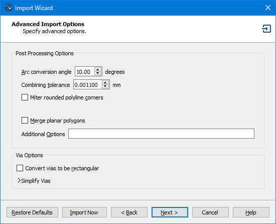
Post Processing Options
Arc conversion angle (DXF only): Enter the angle in degrees used for converting arcs and circles to piecewise line segments. The angle, in degrees, is the step size used to divide up the circle or arc. For example, if the angle is 10, a circle will become 36 line segments. The default is 10. This option only appears for DXF Imports.
Combining tolerance (DXF only): The tolerance used to join nearly touching objects to form a larger polygon. The default is 0.0011.The units used are those selected in Import Options page. This option only appears for DXF Imports.
Miter rounded polyline corners (DXF only): Polyline rounded corners are "mitered". Straight line segments are used instead of the arcs. This option only appears for DXF Imports.
Merge planar polygons: Selecting this option will combine overlapping or touching polygons of the same Tech Layer into a single polygon. Enabling this option often reduces the number of subsections so that your simulation requires less time and memory use. This option only appears for DXF and GDSII imports.
Additional options: This entry should only be used at the direction of Sonnet Support.
Via Options
Convert Vias to Be Rectangular: This option converts vias to rectangular cross-section vias. The width and height of the new rectangular via are set to the width and height of the bounding box which encompasses the original via.
Simplify Vias Section
The Simplify Vias section allows you to simplify via arrays and identify bar vias using an algorithm during translation. See Via Simplification for details.
Import Status Page
The Import Status page is the final page of the Import Wizard.
When this page is opened, the import is executed using all of the settings from the wizard. Progress messages are shown in the output window as the selected translator performs the conversion. Any warning or error messages are also displayed here.
Remember settings: Select this checkbox if you want future imports to use the import settings you just used. Note that if you use a template, these settings will be overridden by the template settings.
Open in Box Resize Mode: If this checkbox is selected, when you click the Finish button, you may resize the Analysis Box.
Save as Template: If you wish to reuse your import settings for future imports, click the Save as Template button to save your stackup, import settings, and project settings (such as frequencies and EM Options) to a project file. On future imports, you may select this file on the first page of the Import Wizard to use it as a template.
Cancel: While the import is being performed, you may click the Cancel button to abort the translation. Once the translation is complete, the Cancel button is replaced with the Finish button.
Finish: To close the Import Wizard and view the translated project, click the Finish button.