Tutorial: Import DXF File
Importing a DXF file requires a DXF Translator license from Sonnet.
This part of the tutorial teaches how to import a DXF file into the project file, part1_settings.sonx, which you created in the first part of this tutorial. The part1_settings.sonx file contains all the settings, such as units, box settings, cell size, material properties, dielectric layers, Tech Layers, frequencies, and EM options. This file is also available in the Getting Started Tutorial example which you may obtain using the Example Browser.
Obtaining the Tutorial Example Files
You need to copy the DXF file (and optionally the part1_settings.sonx file) to your working directory using the Example Browser.
Select Help > Browse Examples from any Sonnet tab.
The Example Browser opens.
Find the Getting Started Tutorial and select it.
You may use the search box or scroll down until you see the Getting Started Tutorial example.
Click the Save button at the bottom of the Example Browser window.
A Save Example window opens with a list of files that will be saved.
Enter or browse for the folder where you wish to place the example files.
Choose a location you can remember.
Click the Save button.
The example files are saved to the specified folder.
Click the Close button.
The Example Browser closes.
Import Wizard
You will use the Import Wizard to import the polygons from the DXF file into your part1_settings.sonx project file.
If you have not already done so, load the part1_settings.sonx project file into the Project Editor.
There are multiple ways to load a project file into the Project Editor. One way is to go to the Session tab and select File > Edit Project > Browse for File(s).
In the Project Editor, select File > Import > DXF.
A browse window appears.
Browse for dxf_layout.dxf and click Open.
The Import Wizard appears.
Import File Page
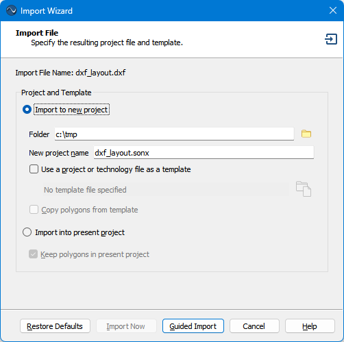
The first page of the wizard is the Import File page. This page allows you to define the output file names, and optional template file, or import the DXF file into your present project.
If it is not already selected, select the Import into present project radio button.
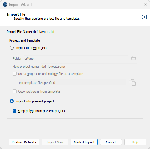 You will be importing the DXF layout into your part1_settings.sonx project. Since there are no polygons in the present project, the checkbox Keep polygons in present project is irrelevant.
The part1_settings.sonx project will not be overwritten by the import unless you intentionally save the project after the import. You will be saving the project as a different name after the import.
If your present project contained all the necessary information to perform an import, the Import Now button would be available. Clicking it would immediately perform the translation and skip the rest of the Wizard. In this case, the layer mapping information needs to be specified, so we will use the Guided Import button.
Click the Guided Import button.
The next page of the wizard, the Import Layer Mapping page, is displayed.
Import Layer Mapping Page
The Import Layer Mapping page is used to map the layers from the source file to Sonnet Tech Layers. The column(s) to the left of the white arrow  refer to the source file and the columns to the right of the white arrow refer to the translated Sonnet project file. The Import Wizard reads the layer information from the source file, then populates the left portion of Layer Mapping page with the layer information.
Select the Map checkbox on the L1, L2, and V1 rows.
This tells the translator to translate these three layers. Any other layers will not be translated.
There are often layers in the DXF file that contain information that is not applicable to an EM solver. Therefore, you should map only applicable layers. In this case, the "0" layer was an empty layer added by the CAD program that created the DXF file, and the "L3" layer contained a solid ground plane polygon. This polygon is not needed because the Analysis Box bottom cover will be used to represent the ground plane.
The Analysis Box covers are part of the boundary conditions of the EM solver and do not require additional computer resources. Therefore, it is always more efficient (and more accurate) to represent a solid ground plane with a box cover than with a polygon.
In the Tech Layer column, select Spiral for L1, Underpass for L2, and Vias for V1 from the corresponding drop-down lists.
The Import Layer Mapping page should look similar to the screen shot below.
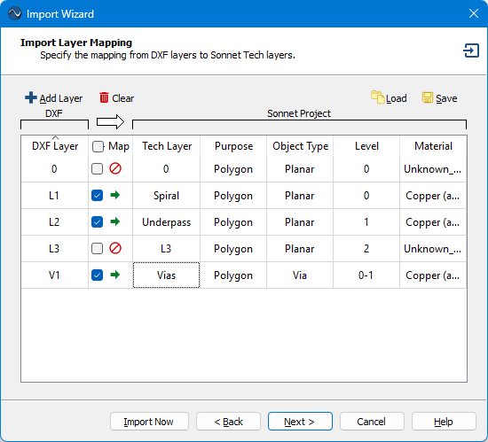
This tells the translator to copy all polygons on DXF layer "L1" to the Sonnet Tech Layer "Spiral", all polygons on DXF layer "L2" to Sonnet Tech Layer "Underpass", and all polygons on DXF layer "V1" to Sonnet Tech Layer "Vias".
You may click on the column headings to sort by that column.
See Editing the Layer Mapping for additional information on the Import Layer Mapping page.
Click the Next button.
The Import Options page is displayed.
Import Options Page
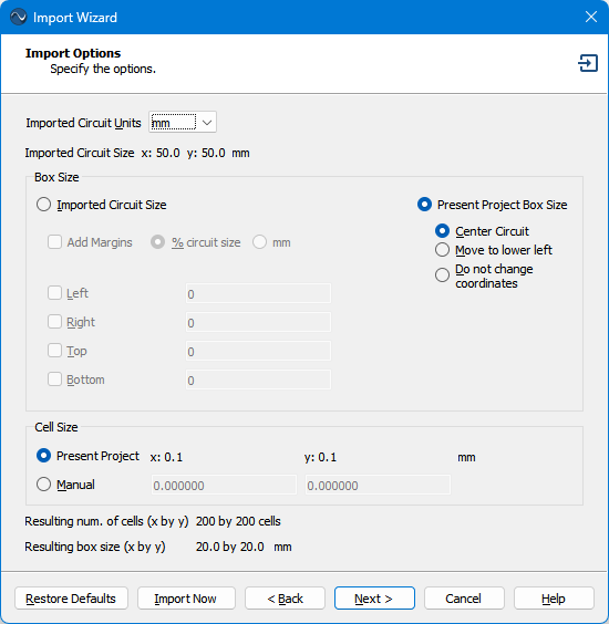
The Import Options page is used to set the units of the DXF file, the translated Analysis Box size, and the translated cell size. See Import Options Page for an explanation of each of these options.
In the Imported Circuit Units drop-down list, select mm.
You may skip this step if the units are already set to mm. The wizard uses previously set values for many of its settings, so this step was included to ensure the correct units.
DXF files do not contain units, so you should always verify that the Imported Circuit Units corresponds to the length unit that was used when the DXF file was created. Note that the extents of the imported circuit in the chosen length units is displayed directly below this drop-down list.
In the Box Size section, select the Present Project Box Size and Center Circuit radio buttons.
You may skip this step if these settings are already set. The Analysis Box size will be the same as the present project and the circuit metal will be centered in the Analysis Box.
In the Cell Size section, select the Present Project radio button.
You may skip this step if these settings are already set. The cell size will be the cell size of the present project (0.1 by 0.1 mm). The Import Options page should look similar to the screen shot below:
Your Import Options are now set up.
Click the Next button.
The Advanced Import Options page is displayed.
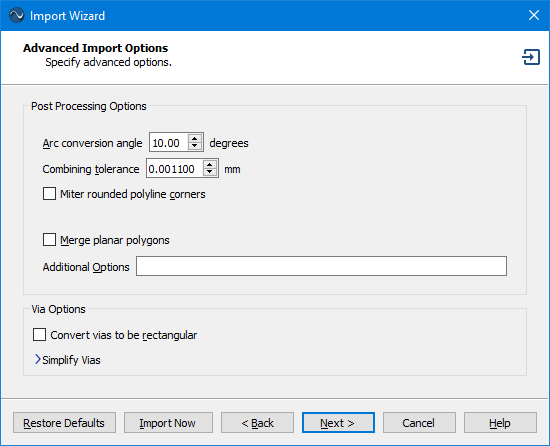
Advanced Import Options Page
The Advanced Import Options page is used for special cases, including cases where you need to simply arrays of vias. The default settings will be used for this tutorial. For more details on this page, see Advanced Import Options Page.
Click the Restore Defaults button at the bottom of the wizard.
This tutorial uses the default settings, and this button sets all the options to their default settings. Since the initial settings on this page depend on previous usage of the wizard, this step is added to maintain consistency between this tutorial and your experience. The settings should match the screen shot below:
Click the Next button.
The Import Status page is displayed and the import starts. Since the DXF file is very simple, the import should be very quick. You should always look for warning messages before continuing. For the tutorial, you should not receive any warning messages.
The Import Wizard defaults to using most of the settings from your most recent import. However, if you ever want to reuse your import settings for future imports, you may click the Save as Template button to save your stackup, import settings, and project settings (such as frequencies and EM Options) to a project file. On future imports, you may select this file on the first page of the Import Wizard to use it as a template.
Click the Finish button to exit the Import Wizard.
If a message appears regarding resizing the box, you may close it and press the Enter key to exit resizing the box.
You already set the box size while creating the part1_settings.sonx file, so you will not need to set it again.
Post-Import Tasks
After importing your layout, you may need to perform additional tasks before finalizing your project. These tasks could include deleting unnecessary metal, repositioning your circuit, and/or snapping your circuit metal to the analysis grid.
Delete Unnecessary Metal
Some circuits have metal that is not necessary for the performance of the circuit. Removing unnecessary metal from your layout can often improve the efficiency of the EM analysis. In this case, there are four large ground shield polygons surrounding the spiral inductor. The four polygons are highlighted in the picture below:
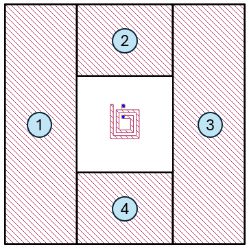
To reduce memory and processing time, you will remove these polygons and the Analysis Box will be used to represent the shield.
Click polygon #1 to select it.
A thick black border indicates that the polygon is selected.
Hold down the Shift key on your keyboard and click the other three polygons.
Holding down the Shift key allows you to add more polygons to your selection without unselecting previously selected polygons.
Press the Delete key on your keyboard.
The four polygons are deleted. Alternatively, you may select Edit > Delete.
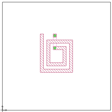
Select View > Full View.
This command resets the area displayed such that the circuit fills the available viewable area. Your circuit should look similar to the picture below:
You may also click the Full View toolbar button  instead of using the menu.
Reposition Circuit Metal
Sometimes, you may wish to reposition the circuit metal within the Analysis Box after you have imported your layout. This circuit is not quite centered in the Analysis Box, so you will center it.
Select Select > Select All.
All polygons in your circuit are selected.
Select Object > Center > Both.
The entire circuit is re-centered within the Analysis Box.
Select Select > Select None.
The selected polygons are unselected.
You may also click any blank area in your circuit to unselect all polygons.
Snap to Grid
This circuit was laid out using a 0.1 by 0.1 mm grid which is the same as this circuit's cell size. However, after the circuit was centered, the circuit is no longer snapped to the grid. This can be seen by zooming up on a portion of the circuit as described next.
Select View > Zoom.
Your cursor changes to the zoom cursor to indicate you are in zoom mode. The purpose of zooming up is to be able to see the cell grid.
Using your mouse, drag a region surrounding the top left portion of your circuit.
The zoom area is indicated in the first picture below, and the second picture shows the view after zooming.
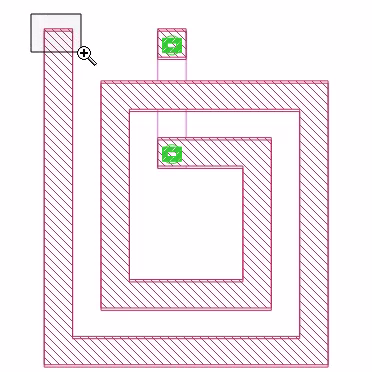
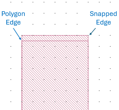
Notice two outlines are shown. The outline labeled "Polygon Edge" represents the exact geometry that you imported. The outline labeled "Snapped Edge" represents the actual subsections analyzed by the EM solver. The fill pattern always corresponds to the actual subsections analyzed by the EM solver. See The Analysis Grid for more details.
You may turn the snapped fill pattern on and off by selecting View > Polygon Fill > Snapped Fill and View > Polygon Fill > No Fill. See Polygon Fill for details and for additional viewing options.
It is not necessary to have all of your metal polygons snapped to the grid because the EM solver analyzes the snapped coordinates. However, it can sometimes be more visually appealing to have it snapped to grid. In the next steps, you will re-align the circuit to be snapped to the grid.
Select Select > Select All.
All polygons in your circuit are selected (even the ones you cannot see).
Only the polygon edges are highlighted with a thick black border. If a snapped edge is not coincident with a polygon edge, it is not highlighted.
Select Object > Snap To.
The Snap To dialog box appears.
When you snap a circuit to the grid, you have a choice of snapping each vertex on all the selected polygon(s) to the grid or selecting a reference point to snap and having all other vertices maintain their position relative to that reference point. You will use the second mode.
Click the Select Reference Polygon Vertex button.
The dialog box temporarily disappears and your cursor changes.
Click the top left vertex of the spiral inductor.
The vertex is selected and the Snap To dialog box reappears. Notice that the the second mode (Preserve shape and spacing relative to the referenced point) is now selected.
Click OK.
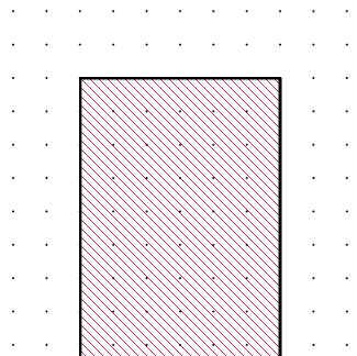
The picture below shows that the previously unsnapped edge is now snapped.
When using the Preserve Shape mode, only the selected vertex is guaranteed to be snapped to the grid.
The entire circuit is now shifted by the same amount that the selected vertex was shifted.
Select View > Full View.
The area displayed is reset such that the circuit fills the available viewable area.
Select Select > Select None.
The selected polygons are unselected.
Save Your Progress
You have finished importing your layout, so it is a good idea to save your project now.
Select File > Save As and save the project as part2_geometry.sonx.
Next, you will finalize your project. Click the Next button below to continue.