Modeled Elements
Toolbar button: 
A Netlist Project may include one or more Modeled Elements (see Netlist Project Overview). A Modeled Element is an ideal element, such as a resistor, capacitor, inductor, or transmission line, which has a closed-form solution.
The following is a list of Modeled Elements which may be added to a netlist project. Each one contains a definition and the abbreviation used in the Netlist Project Editor. Unless otherwise noted, the units for each parameter are the project's units, which are set using Circuit > Settings > [Units].
Capacitor
Abbreviation: CAP
Definition: An ideal lumped capacitor
Parameters: There is one parameter available in the Element Parameters section of the dialog box:
- Capacitance: The capacitance of the capacitor
CC Current Source
Abbreviation: CCCS
Definition: A current controlled current source. A schematic of the element with the nodes numbered is shown below.
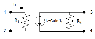
Parameters: There are three parameters available in the Element Parameters section of the dialog box:
- Resistance1: Primary resistance, R1
- Resistance2: Secondary resistance, R2
- Gain: The ratio of the output current to the input current (see diagram above)
CC Voltage Source
Abbreviation: CCVS
Definition: A current controlled voltage source. A schematic of the element with the nodes numbered is shown below.
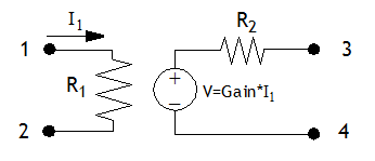
Parameters: There are three parameters available in the Element Parameters section of the dialog box:
- Resistance1: Primary resistance, R1
- Resistance2: Secondary resistance, R2
- Gain: The ratio of the output voltage to the input current (see diagram above)
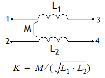
Coupled Coils
Abbreviation: MUC
Definition: Mutually coupled coils. A schematic of the element with the nodes numbered is shown below.
 Parameters: There are four parameters available in the Element Parameters section of the dialog box:
- Inductance1: Primary inductance, L1
- Inductance2: Secondary inductance, L2
- Mutual Inductance: The mutual inductance, M
- Coupling Parameter: The coupling parameter, K
You may enter either the mutual inductance, M, or the coupling parameter, K. The two values are related by the equation shown above.
Inductor
Abbreviation: IND
Definition: An ideal lumped inductor
Parameters: There is one parameter available in the Element Parameters section of the dialog box:
- Inductance: The inductance of the inductor
Resistor
Abbreviation: RES
Definition: An ideal lumped resistor
Parameters: There is one parameter available in the Element Parameters section of the dialog box:
- Resistance: The resistance of the resistor
Transmission Line
Abbreviation: TLIN
Definition: An ideal transmission line specified by its electrical parameters
Parameters: There are three parameters available in the Element Parameters section of the dialog box:
- Impedance: The characteristic impedance of the transmission line
- Electrical Length: The electrical length of the transmission line
- Frequency: The frequency where the electrical length of the transmission line is evaluated
Transmission Line Physical
Abbreviation: TLINP
Definition: An ideal transmission line specified by its physical parameters
Parameters: There are five parameters available in the Element Parameters section of the dialog box:
- Impedance: The characteristic impedance of the transmission line
- Length: The physical length of the transmission line
- K: The effective dielectric constant of the physical transmission line
- Frequency: The frequency where the attenuation is evaluated
- Attenuation: The real part of the propagation constant in dB/unit length at the frequency specified above. The transmission line’s attenuation is frequency dependent and is proportional to the square root of frequency. For example, if your project’s length units are microns, specifying an attenuation of 0.002 and a frequency of 4.0 GHz means a 100 micron long line will have an attenuation of 0.2 dB at 4.0 GHz, 0.1 dB at 1.0 GHz, and 0.4 dB at 16.0 GHz.
VC Current Source
Abbreviation: VCCS
Definition: A voltage controlled current source. A schematic of the element with the nodes numbered is shown below.
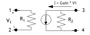
Parameters: There are three parameters available in the Element Parameters section of the dialog box:
- Resistance1: Primary resistance, R1
- Resistance2: Secondary resistance, R2
- Gain: The ratio of the output current to the input voltage (see diagram above)
VC Voltage Source
Abbreviation: VCVS
Definition: A voltage controlled voltage source. A schematic of the element with the nodes numbered is shown below.
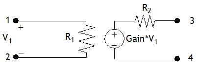
Parameters: There are three parameters available in the Element Parameters section of the dialog box:
- Resistance1: Primary resistance, R1
- Resistance2: Secondary resistance, R2
- Gain: The ratio of the output voltage to the input voltage (see diagram above)