Dimension Parameters
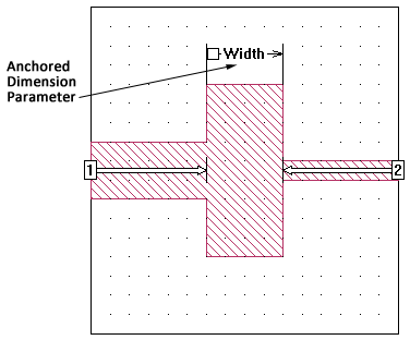
A Dimension Parameter allows you to identify dimensions in a geometry project and assign a variable to the dimension, which permits you to vary those dimensions within an analysis. The initial value of the Dimension Parameter is the length that appears in your circuit. This is the nominal value of the variable assigned to the Dimension Parameter. If you change the nominal value of the variable, then the circuit is redrawn with the new value.
There are three types of Dimension Parameters:
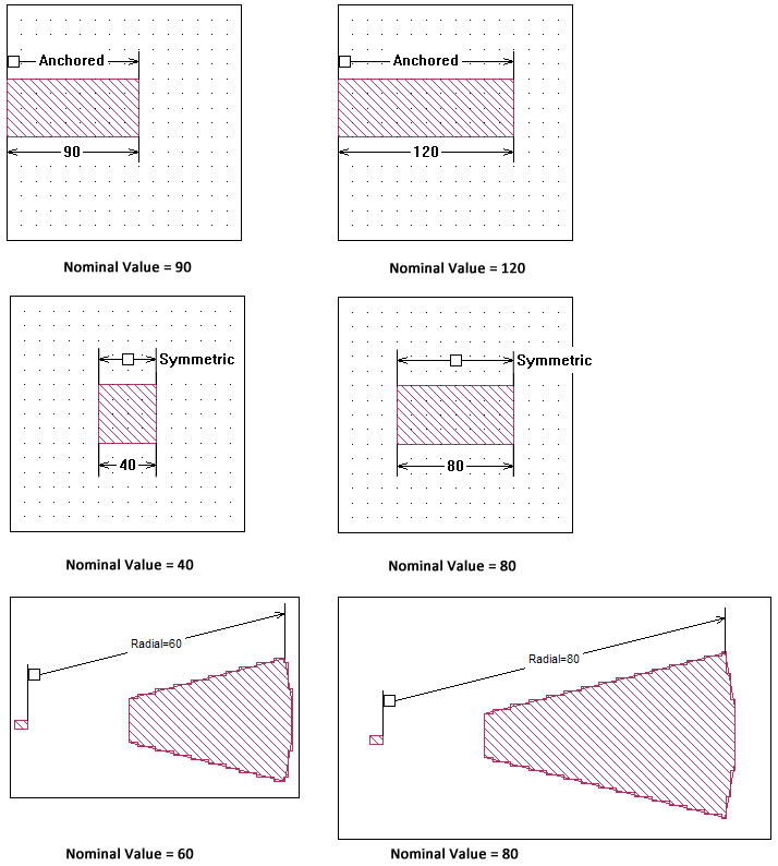
- Anchored: An Anchored Dimension Parameter allows you to fix one end of a parameter then vary its length extending from that point in either the x or y direction.
- Symmetric: A Symmetric Dimension Parameter allows you to fix the center point of a Dimension Parameter and vary the distance it extends on each side in either the x or y direction.
- Radial: A Radial Dimension Parameter allows you to fix one end of a parameter then radiate out from that fixed point. The direction is not restricted to the x or y direction, but may extend at an angle.
The three Dimension Parameter types are described in detail below.
Anchored Dimension Parameters
An Anchored Dimension Parameter uses an Anchor Point, a Reference Point and an Adjustable Point Set. The nominal value of the Dimension Parameter is defined by the distance between the Anchor Point and the Reference Point. When the value of the Dimension Parameter is varied, each point moves relative to the Anchor Point. When defining your Anchored Dimension Parameter, you perform the following steps:
Click the Anchor Point.
This is the fixed starting point for the Dimension Parameter.
Click the Reference Point.
When the value of the Dimension Parameter is changed, the Anchor Point retains the same position, but the Reference Point moves to a new position.
Select any Additional Points in your circuit you wish to move when the Reference Point moves.
This is the Adjustable Point Set. As the value of the Dimension Parameter varies and the Reference Point is moved, the positions of the points in the Adjustable Point Set also move.
Test the Dimension Parameter after creating it by clicking the Test button.
This temporarily adjusts the Dimension Parameter over a range of values and graphically displays the effect on your geometry.
Note that the Anchored Dimension Parameter is always defined as the distance between the Anchor Point and the Reference Point in either the X direction or the Y direction, never as a diagonal distance between them. See Movement of Adjustable Point Sets for advanced options for controlling how the Adjustable Points move when the value of the Dimension Parameter changes. Two examples are illustrated below which use the default setting for how the Adjustable Point Set moves.
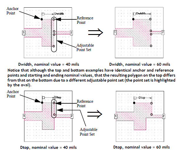
If you wish to change the Adjustable Point Set, select the Dimension Parameter and select Object > Modify Point Set. You may then use the Shift and Ctrl keys to modify the Point Set (see Shift and Control Keys).
Symmetric Dimension Parameters
A Symmetric Dimension Parameter uses two Reference Points and their respective Adjustable Point Sets. The nominal value of the Dimension Parameter is the distance between the two Reference Points. The Anchor Point is defined as the midpoint between the two Reference Points; the user does not define an Anchor Point for a Symmetric Dimension Parameter. When the value of the Dimension Parameter is varied, each point moves relative to the Anchor Point. When defining your Symmetric Dimension Parameter, you perform the following steps:
Click the first Reference Point.
Select the Adjustable Point Set that moves with the first Reference Point.
Click the second Reference Point.
The value of the Dimension Parameter is the distance between the two Reference Points.
Select the Adjustable Point Set that moves with the second Reference Point.
Test the Dimension Parameter after creating it by clicking the Test button.
This temporarily adjusts the Dimension Parameter over a range of values and graphically displays the effect on your geometry.
Note that the Symmetric Dimension Parameter is always defined as the distance between the Reference Points in either the X direction or the Y direction, never as a diagonal distance between them. See Movement of Adjustable Point Sets for advanced options for controlling how the Adjustable Points move when the value of the Dimension Parameter changes. Two examples are illustrated below. This example uses the default setting for how the Adjustable Point Set moves.
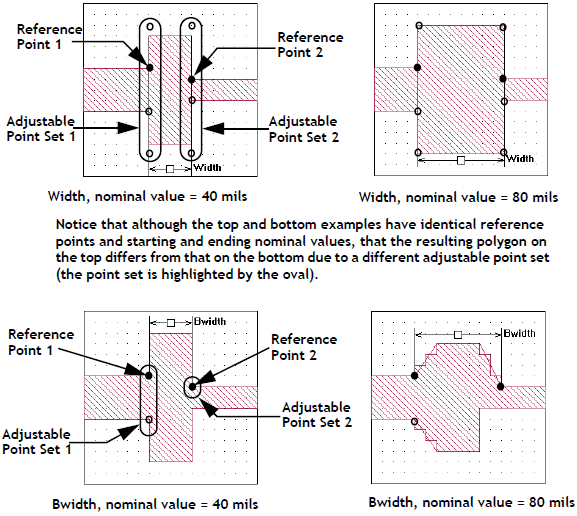
If you wish to change the Adjustable Point Set, select the Dimension Parameter and select Object > Modify Left Point Set or Object > Modify Right Point Set. You may then use the Shift and Control keys to modify the Point Set (see Shift and Control Keys).
Movement of Adjustable Point Sets
The Action setting controls how the Adjustable Point Sets of Anchored and Symmetric Dimension Parameters are moved.
Below is shown the Parameter Properties dialog box in which you select the option from the drop-down list. This dialog box appears when you are creating a Dimension Parameter or when you select Object > Parameter Properties when a Dimension Parameter is selected.
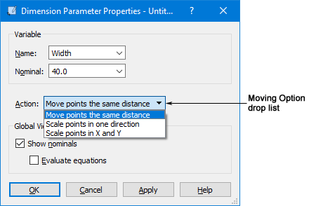
Each option is explained in detail below.
Move Points the Same Distance
This setting moves the Adjustable Point Set the same distance that the Reference Point is moved and all the points in the Adjustable Point Set maintain their relative position. This is the default setting. An example using an Anchored Dimension Parameter is shown below. Note that the Adjustable Point Sets are highlighted.
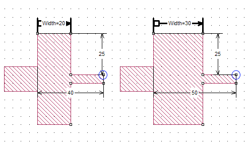 The Anchored Dimension Parameter is increased by 10 microns, so each point in the Adjustable Point Set is moved away from the Anchor Point by 10 microns. As shown in the illustration, the original distance from the anchor to the circled point was 40 microns; when the value of the parameter is increased, the point moves by 10 microns so that it is now 50 microns away from the Anchor Point.
Scale Points in one direction
When using this setting, the geometry is scaled or stretched along either the x or y axis depending on the orientation of the Dimension Parameter. Each point in the Adjustable Point Set is moved by an amount based on its relative distance from the Anchor Point. Points closer to the Anchor Point are moved a smaller distance then points further away from it. For Symmetric Dimension Parameters, the Anchor is the center point between the two Reference Points.
The scaling factor used is the ratio of the new nominal value to the original nominal value. Each point is moved by a distance calculated by multiplying its present distance from the Anchor Point by the scaling factor.
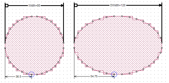
Scale Points in x and y
When using this setting, the geometry is scaled or stretched along both the x and y axes keeping the proportions of the geometry the same. Each point in the Adjustable Point Set is moved by an amount based on its relative distance from the Anchor Point. Points closer to the Anchor Point are moved a smaller distance than points further away from it. For Symmetric Dimension Parameters, the Anchor Point is the center point between the two Reference Points.
The scaling factor used is the ratio of the new nominal value to the original nominal value. Each point is moved by a distance calculated by multiplying its present distance from the Anchor Point by the scaling factor.
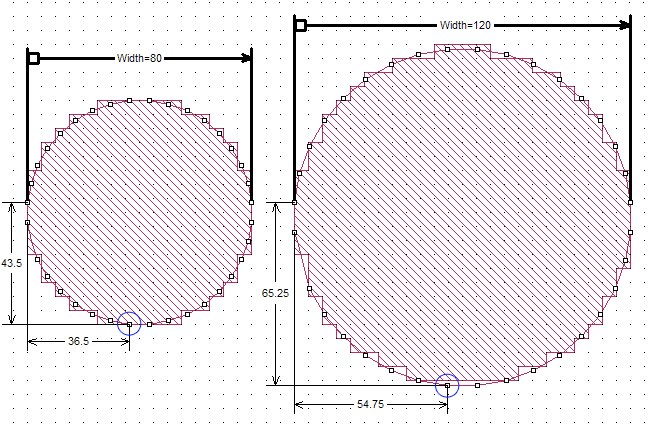
An Anchored Dimension Parameter being scaled in both directions is shown below. The scaling factor is 1.5 since the new nominal value is 120 mils and the original value is 80 mils. As shown in the illustration, the original distance from the Anchor Point of the circled point was 36.5 mils along the x axis and 43.5 mils along the y axis; when the value of the parameter is increased, the point is moved to 54.75 mils away from the Anchor Point along the x axis and 65.25 mils along the y axis; the original distances multiplied by the scaling factor of 1.5.
Radial Dimension Parameters
A Radial Dimension Parameter uses an Anchor Point, a Reference Point and an Adjustable Point Set. The nominal value of the Dimension Parameter is defined by the distance between the Anchor Point and the Reference Point. When the Dimension Parameter value is varied, each point moves along a line extending from the Anchor Point through its original position. Setting up a Radial Dimension Parameter is identical to setting up an Anchored Dimension Parameter. When defining your Radial Dimension Parameter, you perform the following steps:
Click the Anchor Point.
This is the fixed starting point for the Dimension Parameter.
Click the Reference Point.
When the value of the Dimension Parameter is changed, the Anchor Point retains the same position but the Reference Point moves to a new position.
Select any Additional Points in your circuit you wish to move when the Reference Point moves.
This is the Adjustable Point Set. As the value of the Dimension Parameter varies and the Reference Point is moved, the positions of the points in the Adjustable Point Set also move.
Test the Dimension Parameter after creating it by clicking the Test button.
This temporarily adjusts the Dimension Parameter over a range of values and graphically displays the effect on your geometry.
An example of a Radial Dimension Parameter set to 40 mils and 80 mils is shown below.
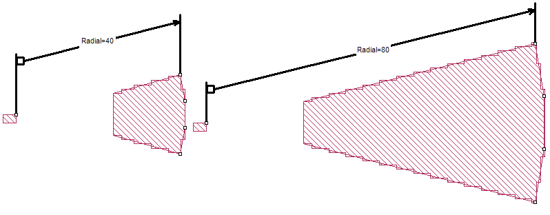
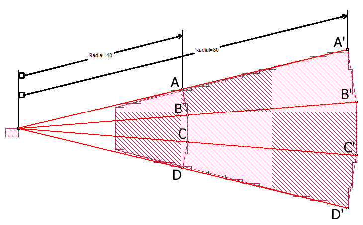
The view of Radial=40 mils is superimposed over the view of Radial=80 mils. Each Adjustable Point moves the same distance along its radius from the Anchor Point to its new position. Therefore line segments AA’, BB’, CC’ and DD’ are all equal to 40 mils, the difference between the two values of the Dimension Parameter Radial.
If you wish to change the Adjustable Point Set, select the Dimension Parameter and select Object > Modify Point Set. You may then use the Shift and Control keys to modify the Point Set (see Shift and Control Keys).
Reference Planes
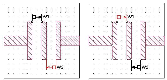
Linking your reference plane to a Dimension Parameter moves the reference plane in response to a change in the Dimension Parameter helping to ensure correct placement of your reference plane. In order to do this, link your reference plane to a point in the Adjustable Point Set as illustrated below.
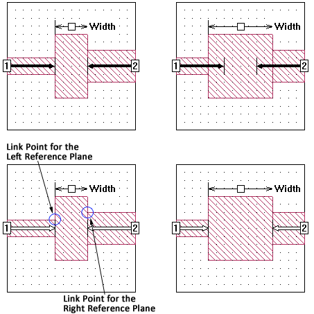 In the circuit shown at the top, the reference planes are a fixed length. When the Dimension Parameter changes, the reference plane lengths do not change, resulting in incorrectly placed reference planes.
In the bottom circuit, the reference planes are linked to points in the Adjustable Point Set. When the Dimension Parameter is changed, the reference planes move with it, keeping the reference planes in the correct place.
Dependent Dimension Parameters
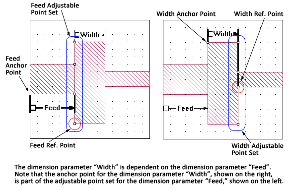
One Dimension Parameter is dependent upon another if the Anchor Point and/or the Reference Point(s) for the second parameter are part of an Adjustable Point Set for the first parameter. This is allowed as long as a circular dependency is not formed (see Circular Dependencies). When the primary Dimension Parameter is changed, a dependent parameter is adjusted; i.e., the Anchor Point or Reference Point is moved, along with the primary Dimension Parameter on which they depend. A picture of a dependent Dimension Parameter is shown below with the Anchor and Reference points highlighted as well as the Adjustable Point Sets.
You may use the Select Dependents command in the Project Editor to determine if there are any dependent Dimension Parameters:
Right-click on a Dimension Parameter in your circuit.
The variable name and the Dimension Parameter's Adjustable Point Set is highlighted and a pop-up menu appears on your display.
Click Select Dependents from the pop-up menu.
If any dependent Dimension Parameters are present in your geometry, the dependent Dimension Parameter is highlighted.
Alternatively, you could select the Dimension Parameter and select Select > Select Dependents.
Circular Dependencies
Care should be taken when adding Dimension Parameters to your circuit that they do not form a circular dependency. A circular dependency is formed when two Dimension Parameters are dependent on each other. This can happen for two Dimension Parameters or multiple Dimension Parameters. In the case of multiple Dimension Parameters, the dependency extends from the first Dimension Parameter through all the Dimension Parameters until the last Dimension Parameter is dependent upon the first.
If the Project Editor detects a circular dependency of Dimension Parameters, all the involved Dimension Parameters are shown in red. An example of a circular dependency is shown below.
 A circular dependency is an error condition and must be corrected before analyzing your circuit.