Benchmarking
Evaluation of Electromagnetic Software
Revised: June 4, 1997
© Copyright 1994, 1999 Sonnet Software, Inc. All Rights Reserved
Table of Contents
Chapter 1 - Introduction
Chapter 2 - Technical Overview
Chapter 3 - The Stripline Standard
Chapter 4 - The Stripline Standard and Triangular Subsections
Chapter 5 - The Microstrip Standard
Chapter 6 - The Coupled Microstrip Standard
Chapter 7 - Limit Tests
Chapter 8 - Lossy Ground Plane and Lossy Dielectric Tests
Chapter 6 - The Coupled Microstrip Standard
The previously described Microstrip Standard quantifies analysis error due to dispersion. Implicit in this is that the analysis de-embedding is working properly. However, the Microstrip Standard requires a properly functioning de-embedding only for single, uncoupled, microstrip lines. Since most electromagnetic de-embedding algorithms are capable of de-embedding through coupled lines, it would be nice to have a standard which checks for error due to improperly de-embedded coupled lines.
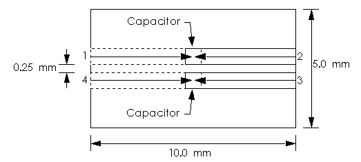
Such a standard is easily generated based directly on the single line coupled microstrip standard. To create the standard, simply duplicate the Microstrip Standard described in the previous chapter. The cross sectional geometry is the same as for the microstrip standard (Figure 7 in Chapter 5) and a top view is shown in Figure 10. The gap between the lines is 0.25 mm. The capacitor dimensions remain unchanged. As with the single Microstrip Standard, if the box sidewalls are not present as shown, the useful frequency range of the standard is degraded from about 10 GHz to 5 GHz due to earlier onset of higher order mode propagation.
Sonnet results are shown in Table 2. The percent error (based on linearity of Y22 or Y33) has actually improved slightly. The nature of the percent error is sufficiently similar to the single Microstrip Standard that we can have full confidence that the coupled line de-embedding is fully functional.

Figure 10. A top view of the Coupled Microstrip Standard. It is simply formed from two copies of the single Microstrip Standard.
| Table 2: Sonnet Performance On The Coupled Microstrip Standard | |
| Frequency (GHz) | Percent Error |
| 0.1 | 0.00% |
| 1.0 | 0.00% |
| 2.0 | - 0.02% |
| 3.0 | - 0.02% |
| 4.0 | - 0.02% |
| 5.0 | - 0.02% |
| 6.0 | 0.00% |
| 7.0 | 0.01% |
| 8.0 | 0.28% |
| 9.0 | 0.91% |
| 10.0 | 2.26% |


